Automation of simple two-speed pool pump

My pool pump runs on a Raspberry Pi. Not because I needed it to — a mechanical timer works fine for basic on/off scheduling. But I wanted automatic control over pump speed: LOW most of the time, HIGH on a schedule or on demand, with easy overrides from the equipment pad or my phone. A Pi Zero W later (and, honestly, a bunch of other pieces), and I had a Flask app serving a web UI over the local network, toggling a few GPIO pins on a schedule.
That was about two years ago (summer of 2024). It worked. I left it alone.
Then I decided to make a UI enhancement for the web interface. But perhaps I'm getting ahead of myself... Let's go back to the beginning.
Outline
- The problem — why a dumb timer wasn't enough
- The build — hardware, software, what the UI does
- The refactor — schedule editing, architecture review, tests, module separation
- What broke — prod deployment incident, reboots, diagnosis, root cause theories
- The fix — watchdog config, systemd, wifi recovery
- Where it landed — current state, what's running now
- Want to build this? — key decisions before you start
- Parts used — BOM with pricing
- Resources
The problem
My pump is a 1.5hp manual unit with a three-position switch: off, low, high. It plugs into an outlet at the equipment pad.
The first attempt at automation was a Champlain plug-in outdoor timer that came with the pool kit. Whether it failed or I just got frustrated with it, I eventually replaced it with a BN-LINK 7 Day Heavy Duty Digital Programmable Timer. Both of these could handle the outdoor environment fine. But a 1.5hp pump motor is a real load for a plug-in timer, and neither unit inspired confidence in long-term reliability, or offered me what I really needed.
A plug-in timer controls power to the outlet — it can't touch the speed switch. Whatever position that switch was in when power came on, that's how the pump ran.
For normal filtration, running on LOW is fine — quieter, uses less energy, and 1.5hp on HIGH for hours a day adds up on the electric bill. But LOW doesn't have enough suction for the suction-side vacuum. When I wanted to run that, I'd flip the switch to HIGH manually and let it go. The problem was "let it go" had a way of turning into "forgot about it." Hours became a day. Or days. The pump would run on HIGH until I remembered to flip it back.
What I actually wanted:
- A schedule that runs the pump on LOW during most of the day
- The ability to kick it into HIGH for a set duration — then automatically return to LOW, not off
- A web interface so I could check status and make changes from my phone without walking to the equipment pad
- A physical control panel at the pad for manual overrides without needing a phone
That last part mattered. A web-only interface is fine when everything's working, but if I'm standing at the equipment pad with wet hands, I want a button.
The build
Safety note. This project involves working with mains voltage. Opening a motor control box while it's plugged in, wiring a relay panel to a live circuit, or making a mistake on the line-voltage side of any of this can cause serious injury, death, or equipment damage. This post is written with the assumption that you have working familiarity with electrical systems — how to work safely on them, when to isolate power before touching anything, and when to get help. If you're not there yet, read on, but don't pick up a screwdriver until you are.
The first step wasn't wiring anything — it was opening up the pump to figure out how it actually worked. I didn't already know how the speed control was implemented internally, and maybe you don't either. This is worth doing before you buy a single component, because what you find inside determines your whole approach.
What I found: the terminal box has a small terminal block with separate connections for the LOW and HIGH windings, plus a common. The original speed switch doesn't just control power to the pump — it routes the incoming power to one winding or the other. Flipping it to LOW connects power to the LOW winding; HIGH connects to the HIGH winding. That's the whole mechanism.
That's also the insight that makes external control possible. You don't need to simulate a switch position — you just need to deliver power to the right terminal.
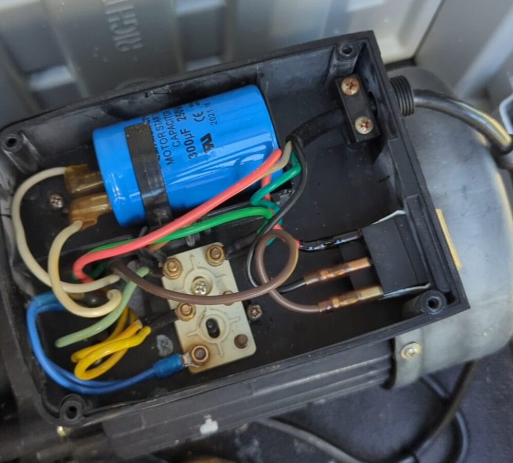
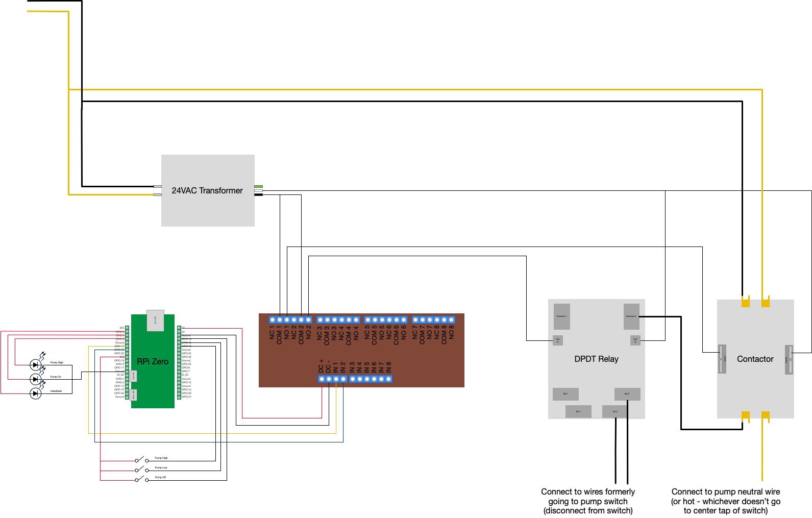
Controlling LOW vs HIGH required thinking through the relay topology before buying anything. You have two basic options: two relays in parallel with the speed switch (one for LOW, one for HIGH), or two relays in series — one that controls power to the pump, and a second that determines whether that power goes to the LOW or HIGH winding. I went with the series approach because it was far less likely — via programming error or mechanical failure — to energize both windings simultaneously.
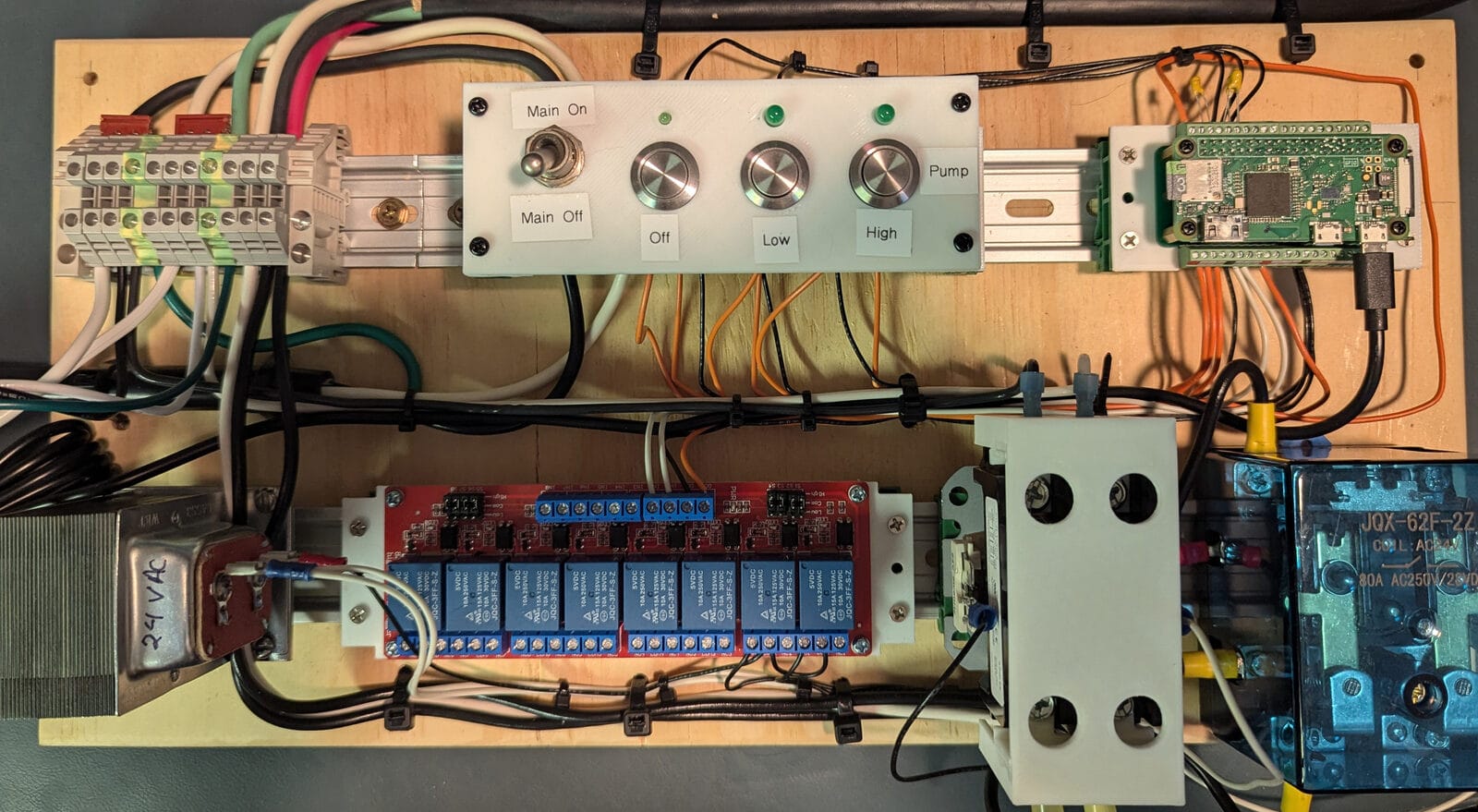
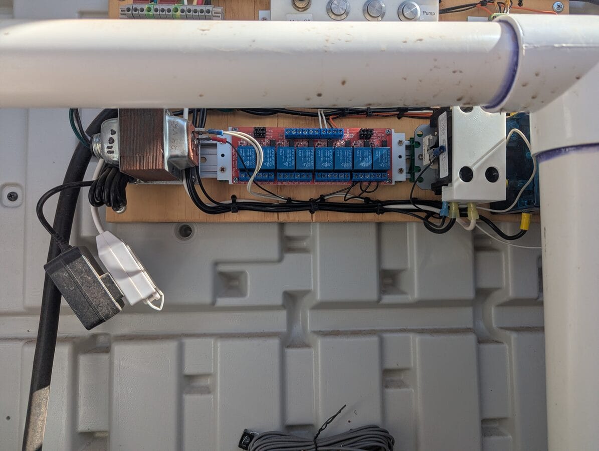
The hardware:
- Power switching: a 30A double-pole HVAC contactor with a 24V AC coil. These are designed for repeatedly switching motor loads. The 24V coil means it needs a transformer, not a direct Pi GPIO connection.
- Speed selection: a high-current 80A DPDT relay, also 24V AC coil. DPDT gives you the two positions (LOW / HIGH) with one relay.
- Pi-side switching: an 8-channel 5V relay module with optocouplers. The Pi GPIO drives these; they in turn control the 24V from the doorbell transformer to energize the coils on the larger relays. I only used 2 of the channels for this, but bought the 8x version planning for possible future expansion. The price difference between a 2-channel and 8-channel version of these devices is small enough that the physical footprint and future plans can be more important than the cost.
- GPIO connection: a terminal block breakout board for the Pi Zero, which makes the wiring to the relay module clean and serviceable.
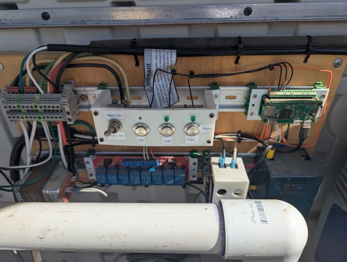
Everything mounts to a piece of plywood via 35mm DIN rails, with DIN rail terminal blocks for all the wire connections. A handful of 3D-printed brackets and shields keep things organized and cover the areas where you could accidentally contact line voltage.
Here's the full Pi Zero W pinout as used in this build (see SparkFun's Pi Zero pinout for reference):
| Usage | Meaning | Pin (odd) | Pin (even) | Meaning | Usage | |
|---|---|---|---|---|---|---|
| Unused | 3.3VDC | 1 | 2 | 5VDC | To DC+ on the relay board | |
| Heartbeat LED indicator | GPIO 2 | 3 | 4 | 5VDC | Unused | |
| Pump On LED indicator | GPIO 3 | 5 | 6 | GND | To DC- on the relay board | |
| Pump High LED indicator | GPIO 4 | 7 | 8 | GPIO 14 | Pump Off Button | |
| Unused | GND | 9 | 10 | GPIO 15 | Pump Low Button | |
| Relay 1 coil (power) | GPIO 17 | 11 | 12 | GPIO 18 | Pump High Button | |
| Relay 2 coil (speed) | GPIO 27 | 13 | 14 | GND | Unused | |
| Relay 3 coil (not used) | GPIO 22 | 15 | 16 | GPIO 23 | Unused | |
| Power for buttons | 3.3VDC | 17 | 18 | GPIO 24 | Unused | |
| Unused | 19–39 | 20–40 | Unused |
The control panel face has two types of inputs: a master toggle switch and three momentary buttons. The toggle switches the incoming line — both hot and neutral — which kills power to the entire panel. The Pi shuts down, the transformer loses power, the relays de-energize. It's intentionally close to unplugging the whole thing, and that's the point. Any time you need to work on the wiring or just want a hard off, one switch does it.
The three momentary buttons are labeled Off, Low, and High and are located next to a "Pump" group label. Each sends a command to the Pi. Above them, three LEDs:
- Above Off: heartbeat — blinks to show the Pi is running
- Above Low: on when the contactor is commanded on — meaning the pump is running at any speed
- Above High: on when the speed relay is commanded high — meaning the pump is specifically on HIGH
When the pump is running on HIGH, both Low and High LEDs are lit. On LOW, only the Low LED is lit. Off, neither.
With the panel in place, the wires run back to the pump. Here's the motor terminal box during and after that work:
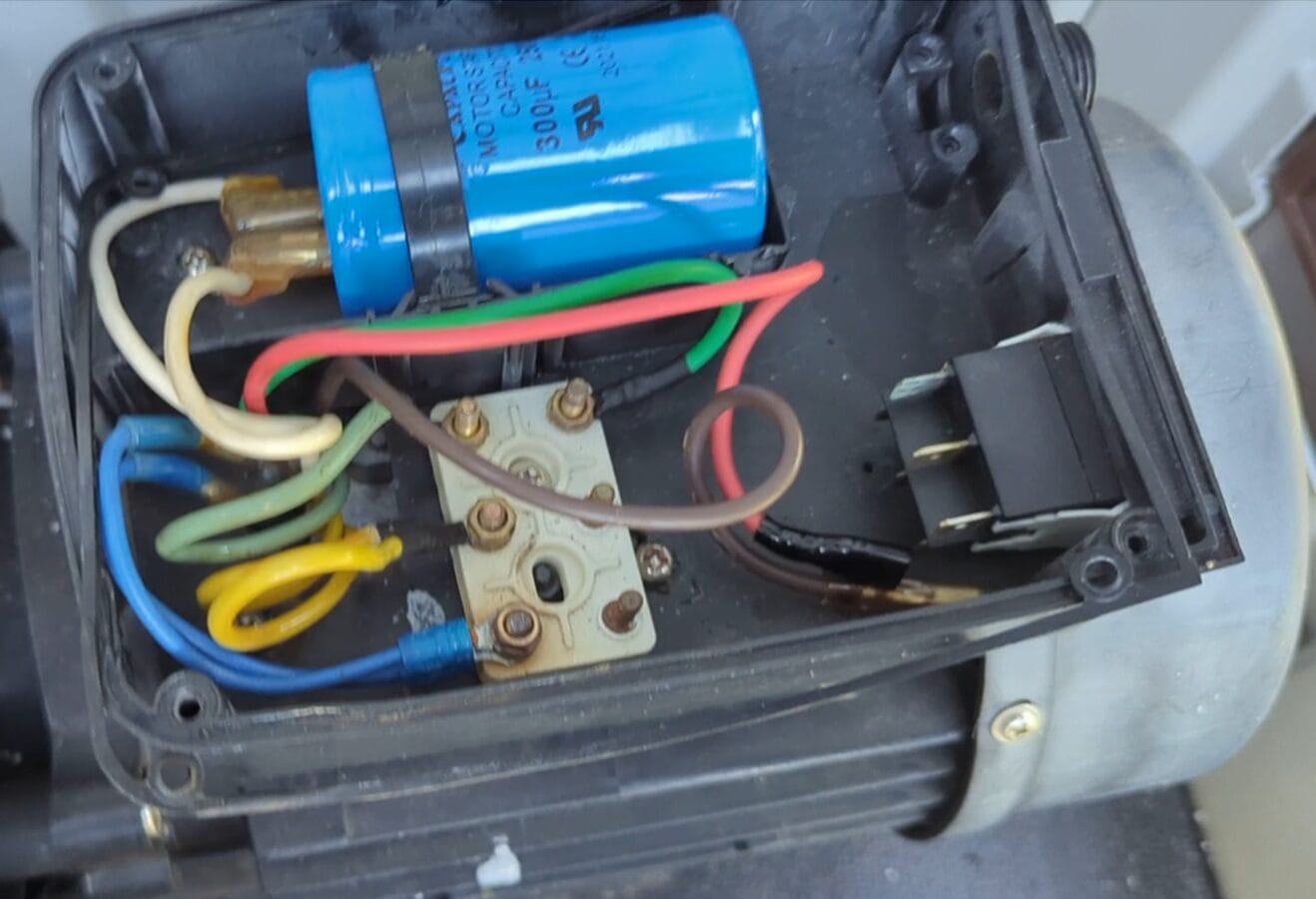
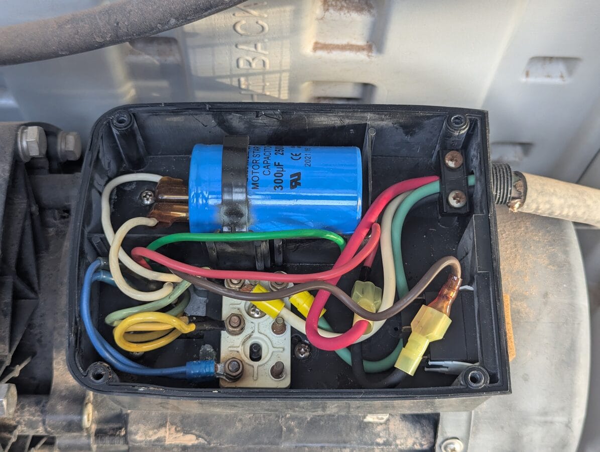
I wired the new control panel leads to match the existing motor wires by color — red to red. That required swapping a couple connections on the DIN terminal block later to make sure "Low" in the software actually corresponded to the low-speed winding and not the other way around.
The panel also controls power to the pool's chemical dosing equipment. When I first installed it, that was a liquid chlorine dosing pump; I later switched to a salt water chlorine generator (SWCG). Either way, the same principle applies: the chemical equipment is wired so it only receives power when the pump is running. It can't run without flow, which matters for both equipment longevity and water chemistry. The SWCG has its own flow detection switch as a secondary safeguard.
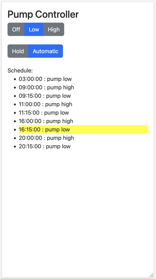
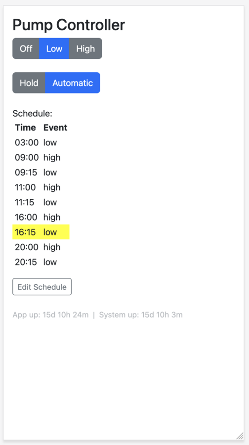
The Pi Zero W connects to the house wifi and runs a Flask app on the local network. The web UI mirrors the physical buttons — Off, Low, High — and adds a few things the buttons can't do.
The web UI displays the current schedule. The default runs the pump mostly on LOW with four 15-minute HIGH bursts during the day:
| Time | Speed |
|---|---|
| 03:00 | LOW |
| 09:00 | HIGH |
| 09:15 | LOW |
| 11:00 | HIGH |
| 11:15 | LOW |
| 16:00 | HIGH |
| 16:15 | LOW |
| 20:00 | HIGH |
| 20:15 | LOW |
The current schedule slot is highlighted so you can see at a glance where the system is in its cycle.
There's also a Hold mode. Pressing Hold keeps the pump in its current state instead of following the schedule — useful when you want the suction cleaner to run for a few hours without the schedule interrupting. Pressing Hold multiple times extends the duration in steps, up to 24 hours; one more press returns to Automatic. The physical buttons don't have this — they override the current state but the schedule resumes at the next event.
The software side when first deployed was three files. components.py was actually reasonable — enums and a generic event-driven Composite class. webapp.py had the Flask routes, scheduler thread, hold logic, and some mutable globals all together. And configure.py was doing double duty: wiring up GPIO on startup and serving as a shared runtime context that everything else imported from. Even at the time, the comment at the top of that file said: "I'm not totally happy with this arrangement... the dependency arrows point both ways... it's a messy mish-mash." The UI was read-only — you could see the schedule, but not edit it. No tests. Flask 1.1.2.
The surrounding infrastructure was a set of shell scripts:
- Deploy: an SSH-based script that wiped the target folder, copied files, stopped the app (via the PID), ran
pip install, configured the watchdog, set up the cron job, and started the app again. - Auto-start:
rc.localranstart_webapp.shon boot, which launchedwebapp.pyin the background and wrote the PID towebapp.pid. - Watchdog: monitored network interface (
wlan0) and load average. Timeout: 15 seconds (the BCM2835 hardware maximum). No process monitoring — if the app crashed, it stayed down. (The BCM2835 hardware watchdog needs to be enabled before any of the software setup will work — adddtparam=watchdog=onto/boot/config.txtand reboot. Check this first.) - Wifi recovery:
check_ping.shran every 5 minutes via cron, pinging the router. If it failed, it ranwpa_cli reconfigureto kick the wifi adapter back to life.
If the app crashed, it stayed down until the next reboot. For two years, it apparently never crashed — or not so I noticed. Sometimes that's enough.
The refactor
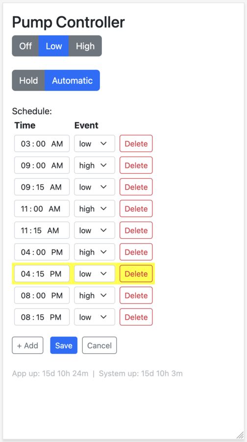
About two years later, I went back into the codebase to add something I thought would add a bit of polish: editable schedules directly from the web UI. Before implementing anything, I looked at what an implementation might look like. Seeing how it would interact with the existing architecture made it clear that configure.py's dual role was going to make any new feature risky to add cleanly. The untested codebase, Flask three major versions behind, no dependency pinning — none of it was stopping the pump from running, but it was the kind of debt that turns a small feature into a project.
So the feature led to a refactor. Tests first — I added a FakeGPIO class so the test suite could run on macOS without hardware, and wrote 28 tests covering routes, rendering, scheduling, and GPIO state. I was using AI to help with this — so while this may sound tedious, the toolset made it much easier to swallow. Then proper module separation: routes.py, gpio_driver.py, scheduler.py, components.py, with main.py as the single wiring point. configure.py was eliminated. Schedule editing was implemented at the same time — with an explicit edit-mode toggle so accidental taps on a phone don't corrupt the schedule.
Then I accidentally deployed to prod before dev — sigh. Both came up clean.
What broke
The Pi Zero W stopped responding. The app had crashed and the Pi had rebooted on its own. A manual reboot fixed it, but it happened again minutes later. SSH still worked; the Pi was online, just not running the app. I reverted to the old branch while I diagnosed it. Dev was mostly rock solid throughout — the Pi 3B is faster hardware and lives indoors on a stronger wifi signal. There may have been the occasional blip, but nothing consistent enough to zero in on. The Zero W out at the equipment shed was where it really showed up.
I pulled the logs with journalctl — used a few different ways throughout — and worked through the usual suspects: ps, dmesg, free -h. OOM — ruled out, memory looked fine. Possible race condition on jobs.json — unlikely. I found a duplicate entry in rc.local (the old startup command was still there alongside the new one) and removed it. I'd also recently added a second wifi network to wpa_supplicant.conf for a network that didn't exist yet — I commented it out as a precaution.
And I found this in /etc/watchdog.conf:
interface = wlan0
Watchdog was configured to reboot if it couldn't reach the network over wifi. The timeout had been set to 60 seconds during the refactoring — premature optimization, perhaps? — but log messages revealed it wasn't working as expected. The BCM2835 hardware watchdog clamps to a maximum of 15 seconds regardless of what's configured; anything over that is ignored.
Honestly, I never pinned down the root cause with certainty. On an embedded device like this, sometimes you can't — you make changes, observe the effect on stability, and reason backward. Two theories:
Wifi flapping. The non-existent second network may have been destabilizing wpa_supplicant, causing brief disconnects, which the watchdog's interface = wlan0 check converted into reboots. Though the wifi instability might itself have been a symptom of reboots rather than a cause — hard to untangle. The flapping could also have just been environmental. The Pi Zero is outside, in a pool shed, far from the wifi access points.
Deploy duration. The deploy script, which had grown more sophisticated over time in an effort to be idempotent, shuts down the app as its first step. On a Pi Zero W, pip install alone takes well over 15 seconds. If the watchdog was monitoring the process PID, the 15-second hardware timeout would fire mid-deploy — before the new app even started — triggering a reboot. Which would interrupt the deploy. Which would reboot the Pi again. This was confirmed later when, after the Poetry migration, I noticed that deploys were taking long enough that the watchdog would have triggered if PID monitoring had been active.
The duplicate rc.local entry may have contributed to the initial crash independently of any of this.
The takeaway isn't a clean root cause. It's: be careful with watchdog config. Consider the whole lifecycle of the device, not just the primary mode. Are there times when wifi is expected to be down? When a process normally expected to be running won't be? When load may spike high? The watchdog is a blunt instrument — useful, but potentially surprising.
The fix
The fix took longer than I'd like to admit — several hours of debugging spread over two days. With no clean root cause to target, the ultimate approach was: unwind the watchdog and startup config completely, confirm stability on the old branch, then reintroduce each piece one part at a time, watching for reboots at each stage.
First, I unwound everything: commented out all watchdog checks, disabled the watchdog service itself, and disabled the ping test that would reinitialize the network stack when pings failed.
Then I added each piece back incrementally, testing carefully after every small change. Was I too cautious? Maybe. Did I have a reason to be? Yes.
The final state: the watchdog is enabled, but monitors only system load, with a 15-second timeout — if the system exceeds the allowable load for 15 seconds, or fails to check in with the watchdog, it reboots. PID/process monitoring was removed entirely (the 15-second hardware timeout makes it incompatible with any deployment that stops the app — pip install alone blows past that window). The wlan interface check was also removed. For wifi recovery, a cron job (check_ping.sh, runs every 5 minutes) is a more appropriate mechanism. App startup was converted from rc.local to a proper systemd service with Restart=on-failure, so the app supervises itself without needing the watchdog as a crutch.
Once stability was confirmed, I sorted out the dependency management — the code had been running with bare pip and no pinning. I evaluated pip-tools and landed on Poetry: created a pyproject.toml, generated a lockfile, and updated deploy.sh to export requirements.txt before pushing. I also upgraded Flask from 1.1.2 to 3.1.3 while I was at it; no code changes required, all tests passed. One wrinkle: the old pip on the Pi couldn't parse the MarkupSafe 3.0.3 source distribution's TOML metadata — fixed by adding pip install --upgrade pip to the deploy script before the dependency install step.
Everything was tagged: v1.0 (pre-refactor), v1.1 (architecture), v1.2 (pinned deps), v1.3 (updated docs), v2.0 (Flask 3 + Poetry).
The deploy script handles the push to either Pi: export requirements from the Poetry lockfile, stop the service, wipe and copy all files over SSH, upgrade pip, install dependencies, and re-run the setup scripts for the service, ping cron, and watchdog. It defaults to the Pi Zero; pass the Pi 3B's IP as an argument to deploy to dev instead.
Where it landed
The Pi Zero has been running cleanly for six weeks since the watchdog fix. The codebase is in a state where I'd be comfortable sharing it — tested, dependency-managed, properly supervised. Schedule editing works from the web UI. The pump runs on time.
It's not a glamorous project. But it's running equipment that runs every day. It's getting the job done. And except when I decide to improve it, it has been solid for two years.
Want to build this?
The specific parts here are sized for a 1.5hp two-speed pool pump, but the pattern applies to a lot of dumb motor loads. If you're looking at something similar — a motor with multiple modes, a load you want on a schedule, something that needs physical and remote control — here's what to think through before you buy anything.
Open the load first. Don't assume you know how the internal wiring works. What I found (separate LOW and HIGH winding terminals on a common) made external control straightforward. What you find determines your whole approach — and might change which components you need entirely.
Think through your relay topology before ordering. If your load has multiple modes, the series approach — one relay for power, one for mode selection — is safer than wiring two relays in parallel. A software bug or relay failure in a parallel topology can energize two things at once. In my case, that means both windings simultaneously, which is bad.
Don't drive high-current loads from GPIO directly. The optocoupler relay module exists for a reason — it isolates the Pi from the load side. For anything with a 24V coil (contactors, DPDT relays), you need a transformer and a suitable intermediate relay stage to drive it.
Enable the hardware watchdog before running the setup script. dtparam=watchdog=on in /boot/config.txt, then reboot. And read the watchdog section above before you configure it — it's easy to misconfigure in ways that cause more problems than it solves.
The full code is at Codeberg. It's set up for this specific hardware but the structure (Flask app, GPIO driver, scheduler, deploy script) is easy to adapt.
Parts used
Prices circa 2024.
Pi & control electronics
- Raspberry Pi Zero W — $25.89
- Pi Zero terminal block breakout board — $17.99
- 8-channel 5V optocoupler relay module — $12.99
- Micro-USB power supply — $11.99
Power switching
- HVAC contactor, 30A double-pole, 24V coil — $13.99
- 80A DPDT relay, 24V coil — $22.99
- 24V 40VA doorbell transformer — $11.99
Panel mounting & wiring
- 35mm DIN rails — $9.99
- 35mm DIN rail mount adapters — $15.99
- DIN rail terminal blocks — $29.89
Panel controls
Also used: plywood for the panel base, 3D-printed DIN rail mounting adapters and safety shields, assorted LEDs and current-limiting resistors, ring and spade terminals, light and heavy gauge wire, a light-duty extension cord modified to provide switched power to the Micro-USB power supply, various other minor items.
Resources
- Web Enabled Pool Control - Raspberry Pi — the Instructables project that sparked this one. I got the general concept here, and likely some early code (I may have also found it republished on a blog somewhere — I don't recall). The project itself is more ambitious than mine; some of its external links are now broken, so the code may not all be accessible.
- Running forever with the Raspberry Pi hardware watchdog — Diode.io. The watchdog setup script was based on this.
- Raspberry Pi GPIO pin reference — Robotics Backend. Used during initial GPIO wiring.
- Project repo on Codeberg — full source, both v1.0 (pre-refactor) and v2.0 (current) tagged.